The Sports Timer Project
Reverse Engineering the display PCB
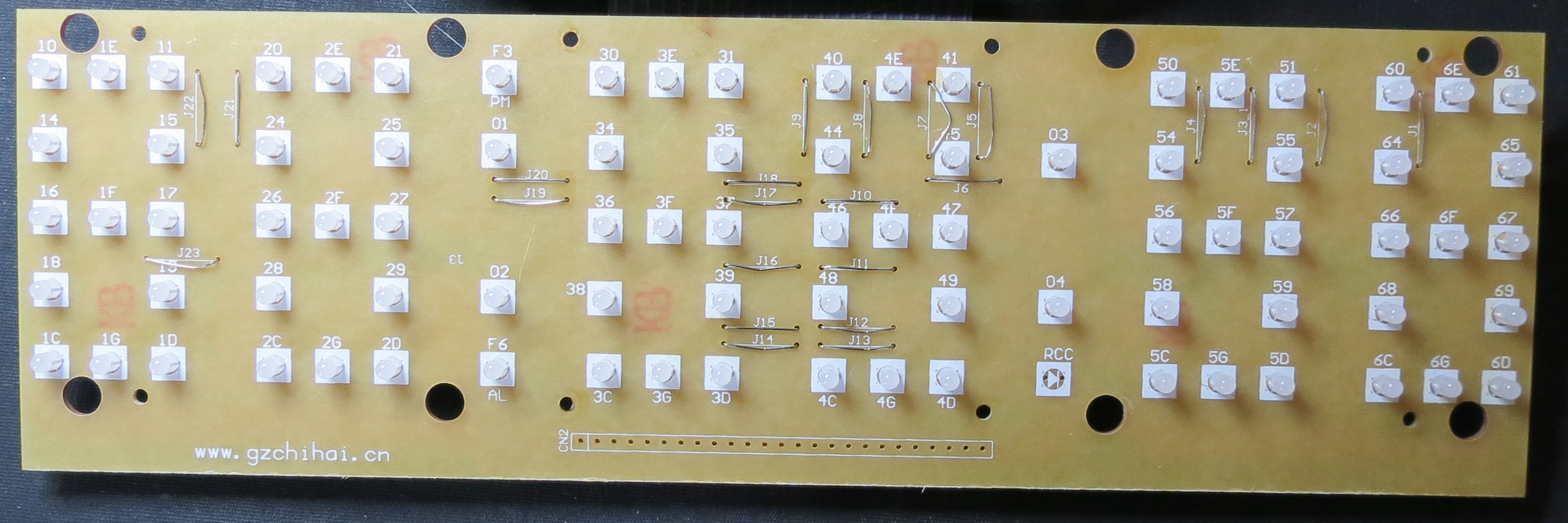
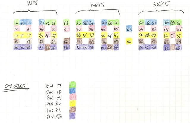
The display PCB has a full six-digits and is connected to the control PCB by a 22-way ribbon cable, I used a DMM to trace the circuitry from each input, there are 16 data bits and six 'scan' bits. I was expecting that each segment would have its LEDs connected in the same pattern however that turnewd out not to be the case so a common look up table for the bit patterns won't be possible. The diagram below shows the relationship between the LEDs and the scan lines, I will publish the full wiring details when I have confirmed them.
Each data line has what looks to be a 27 Ohm resistor for current limiting, at 5V that would give around 140mA or an average of 23mA per LED, this is too much for a PIC to handle so I will use some ULN2803 driver ICs from the parts bin.
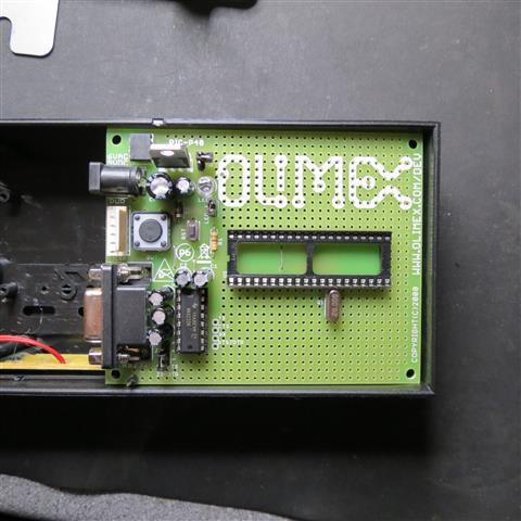
I have decided to use an Olimex PCB for the control board, these boards are intended for development and already have a number of the hardware functions required. It looks like it will be possible to squeeze the complete into the original clock enclosure with just a little trimming.
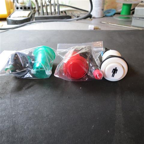
I've also sourced some buttons for use on this project, these are intended for a MAME arcade machine and therefore should have the feel and action required for a button that needs to be pressed many times in quick succession. These will be housed in a die-cast box and I willhave to come up with some kind of mechanism to prevent the reset button from being pressed accidently.
Each data line has what looks to be a 27 Ohm resistor for current limiting, at 5V that would give around 140mA or an average of 23mA per LED, this is too much for a PIC to handle so I will use some ULN2803 driver ICs from the parts bin.
I have decided to use an Olimex PCB for the control board, these boards are intended for development and already have a number of the hardware functions required. It looks like it will be possible to squeeze the complete into the original clock enclosure with just a little trimming.
I've also sourced some buttons for use on this project, these are intended for a MAME arcade machine and therefore should have the feel and action required for a button that needs to be pressed many times in quick succession. These will be housed in a die-cast box and I willhave to come up with some kind of mechanism to prevent the reset button from being pressed accidently.